Guy Cars 1919 – 1925
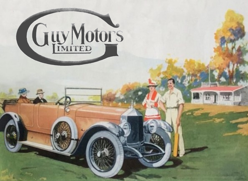
After World War 1 finished in 1918, Sidney Guy decided to expand the range of vehicles and make a car. He drew upon his experience at Sunbeam, a car maker in Wolverhampton where he had been works manager. He had worked with Louis Coatalen, a flamboyant figure in the automotive world, who was interested in the Sunbeam racing cars.
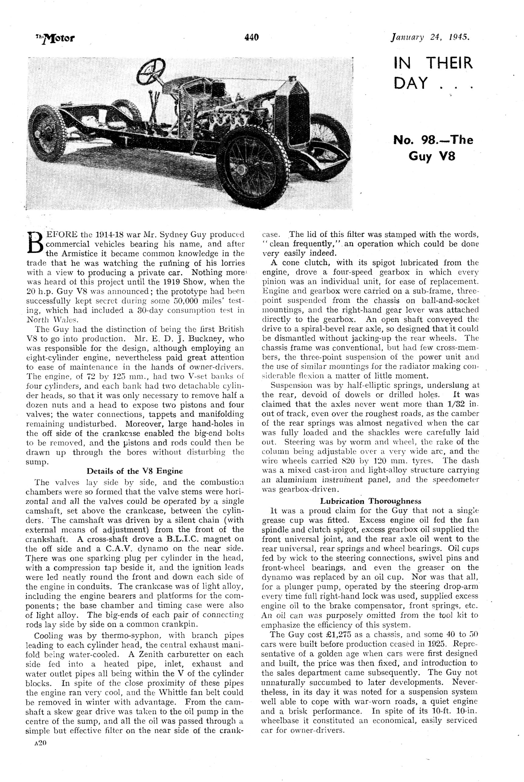
The car turned out to be the first production car in the UK with a V8 engine, released in 1919.
Although up to 50 of the V8 cars were made, none are known to have survived to the present day. There is still some possibility that one may yet be found. Firstly, it is clear form the Motoring in South Africa magazine article that at least one car found it’s way there. Sidney Guy was always keen to do business overseas, and it should be remembered that, at that time, South Africa was an important part of the Empire. Guy soon engaged an agent there to sell trucks and cars. It may be that somewhere in South Africa, there is a barn with a Guy car in it!
A second possibility is equally remote but intriguing. It is reported that a Guy V8 car was used as a “Factory Hack” up until the advent of WW2. Around the same time, It was reported that there was an armoured car prototype that had been produced at the factory, and it was surplus to requirements. It couldn’t be sold, for obvious reasons, and so it was decided to bury it in the “Top Field” where finished vehicles were parked. There was a need to enlarge the field and flatten is out and so a lot of scrap was buried there, including the armoured car. This was told to myself and other apprentices by Frank Boyden, who was Works Manager in the early 70’s. He was an apprentice during the war years and remembered the armoured car being buried. Maybe the “Factory Hack”V8 was buried in there too.
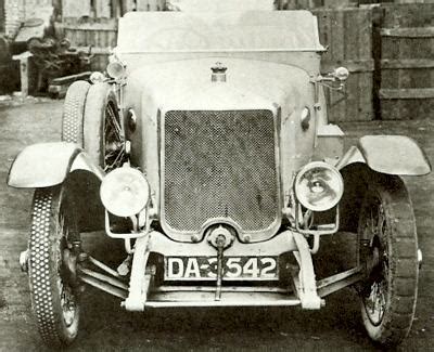
Here is a picture of a Guy 20Hp V8, which may be of the “Factory Hack” car. One clue is that the registration plate (DA 3542) is the same as that seen in many of the pictures of the Guy V8 car, which makes it likely it was a Demonstrator/ Test car, owned by the factory. Therefore it would have been difficult to sell it on. There may also have been some reluctance to part with it.
Also, in this picture, the car seems to be in a slightly neglected state. The front tyres are not a matching pair, and tread on one of them is lacking. The background of the picture seems to show an untidy corner of a factory, maybe.
Here below are some articles appearing in the press at the time of the car’s launch.
Motor Commerce on October 25th 1919.
Motoring South Africa April 1st 1921
And here is an article from Motor Magazine on January 24th 1945
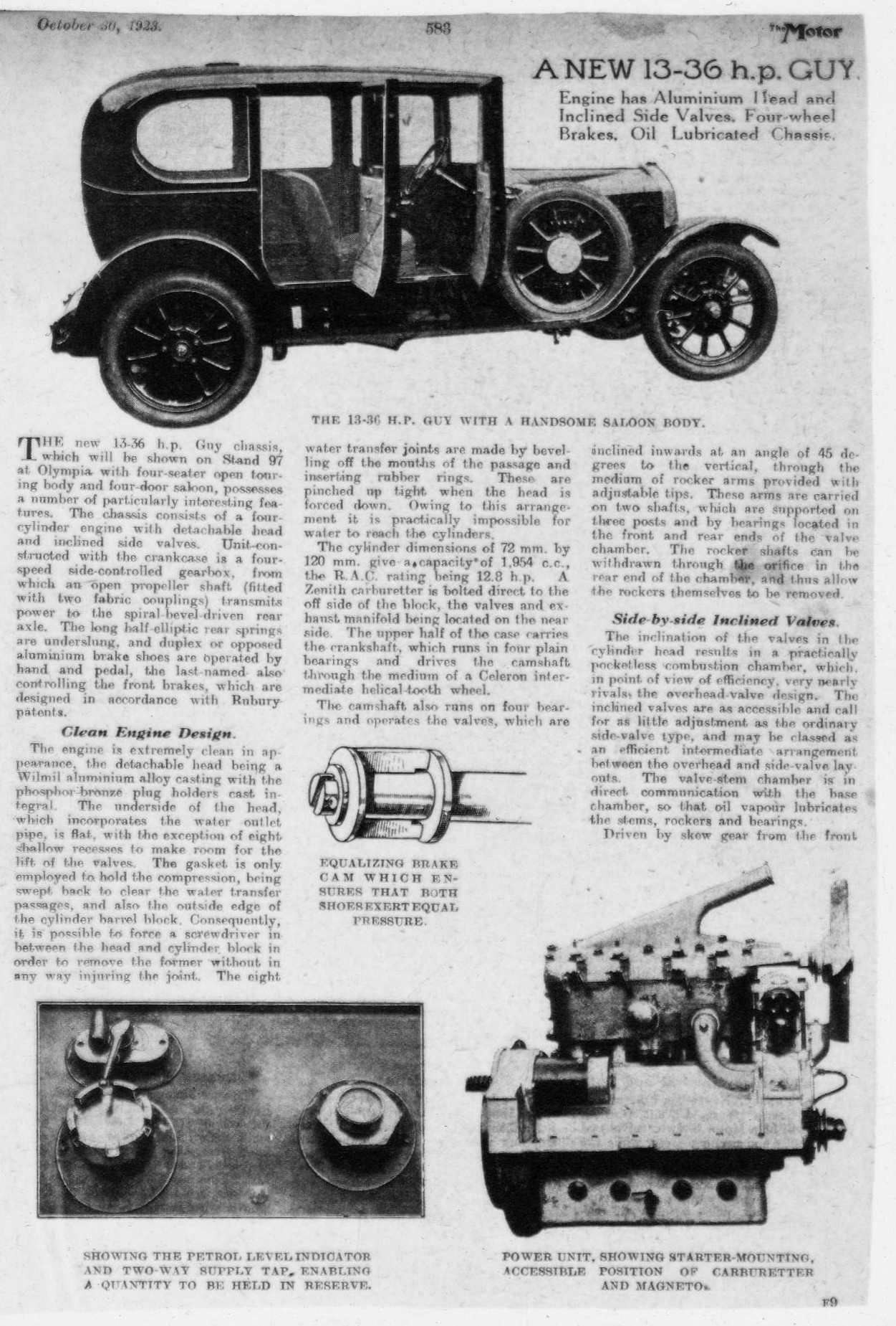
Later, there was a smaller car which arrived in 1923. Here is a link to the Motor article of the time.
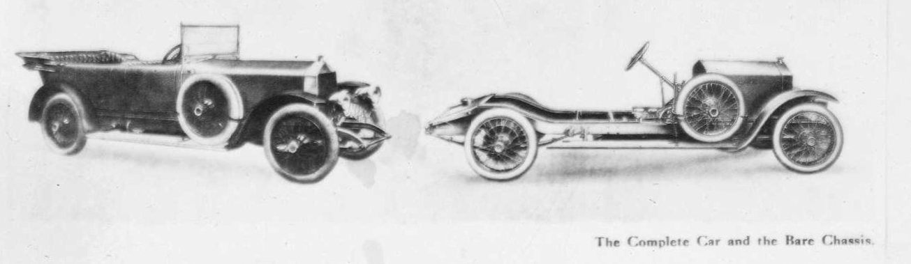
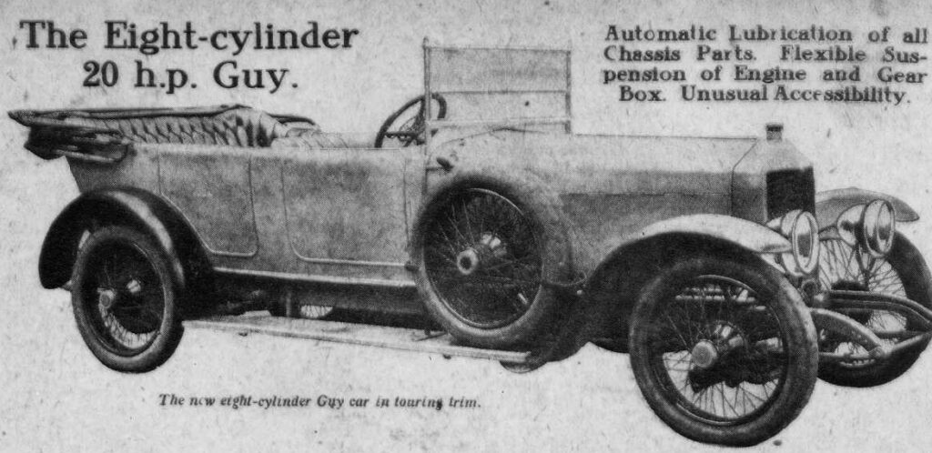
An Eight-Cylinder Guy Chassis
A car pre-eminently for the Owner-driver shortly to be marketed by the makers of the well -known Guy Commercial Vehicles.
We were able a few days ago, owing to the courtesy of Mr. Sydney Guy, to examine the new eight-cylinder 20 h.p. chassis which is to be manufactured by the well-known firm of Guy Motors, Ltd. Wolverhampton, and which is a departure from their normal production. The firm started business in June, 1914, since which date they have flourished exceedingly, and the Guy commercial chassis is now one of the best known of its kind in the country.
Desiring further laurels in the motor field Mr. Guy designed the eight-cylinder car, and for the last 18 months it has been undergoing the most stringent tests at his hands.
From these it has emerged so triumphantly that it has been decided to market it, and in consequence it will be on view this year at Olympia, where it should prove a most interesting exhibit both from the point of excellence workmanship and originality of design. The model which we examined was one of the chassis intended for Olympia, and fortunately for us, was not completely assembled, so that we were able to examine very closely details which would not have been possible in the short time at our disposal, if the chassis had been completed.
A Well thought-out Engine.
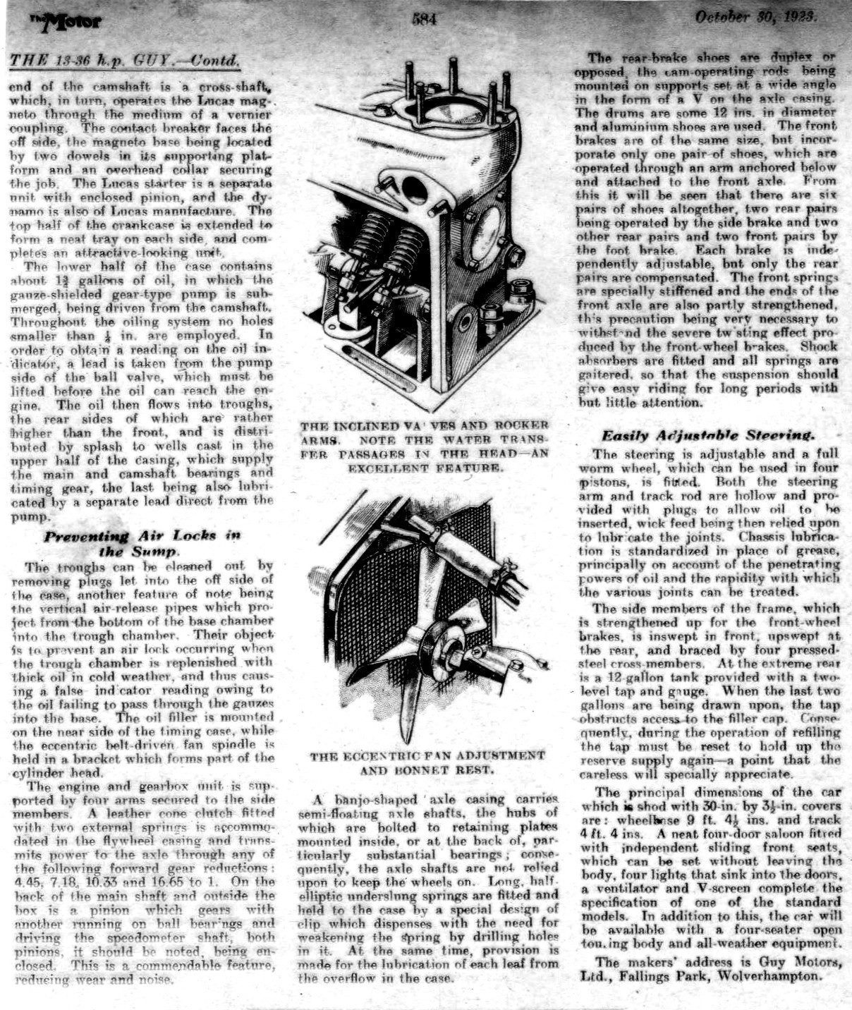
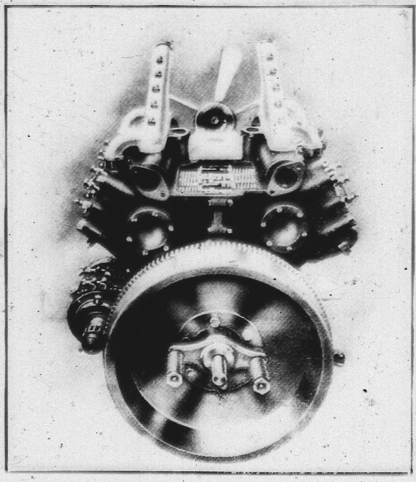
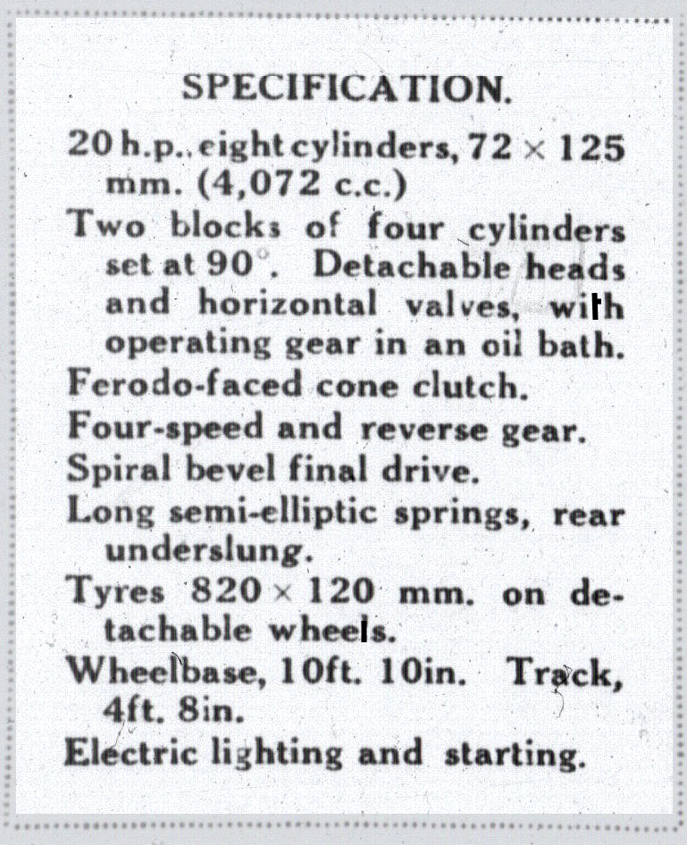
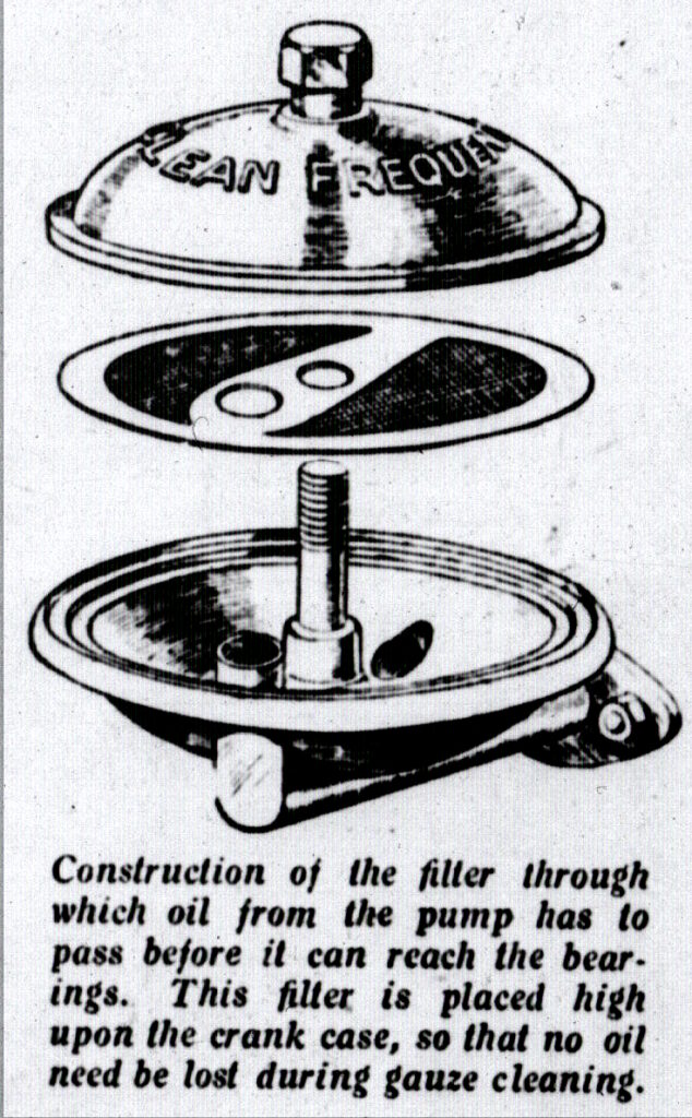
The engine is an eight-cylinder of the V type, two blocks of four set at an angle of 90 degrees. The bore and is 72 mm. by 125 mm., so that it comes within the six tax class. An excellent point, is that the two cylinders bolt together and thereby relieve the crank-case of a deal of stress. Detachable cylinder heads are provided, removal of which exposes the valves and piston thereby rendering valve grinding and decarbonizing an easy matter. The valves, which are horizontal, are operated by rocker; working directly on to the valve stems, provision being made for adjustment. The camshaft runs down the centre of the cylinder blocks, and the whole of the mechanism is enclosed by means of a horizontal plate between the cylinder blocks. The exceptionally good clean design of the combustion chamber can be readily seen from our illustration showing the off-side of the engine. That this design is possible is due to the employment of the horizontal valves, which give all the advantages of overhead valves with none of the disadvantages of that type. Another point upon which Mr. Guy is to be congratulated is in providing adequate means for the automatic lubrication not only of the valve mechanism but valve stems as well. This is done by situating the crankcase breathers on the top of the crank-case, the oil vapour therefore forced directly on to the valve stems and operating mechanism, where it condenses. Any surplus naturally drains back into the crank-case. The lubrication engine itself is by force feed, from a gear pump situated in the sump, to the crankshaft, which is hollow, An oil filter of large size is used, which is very accessible for cleaning purposes.
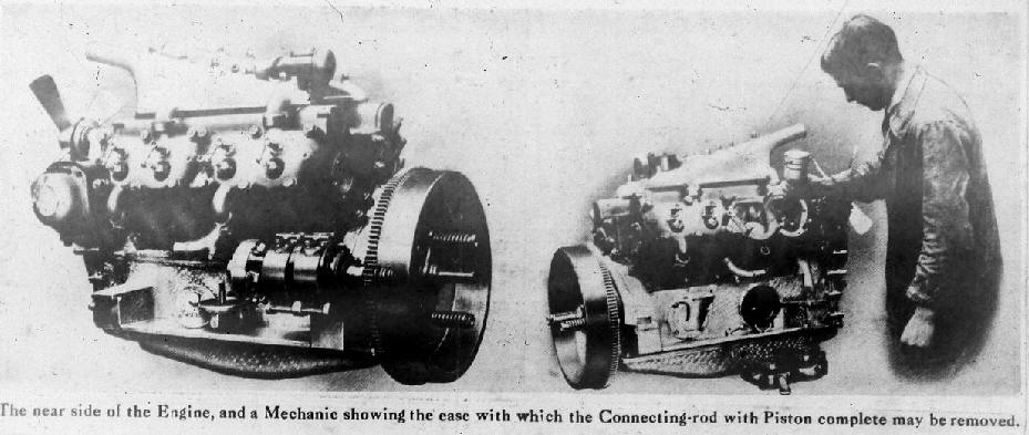
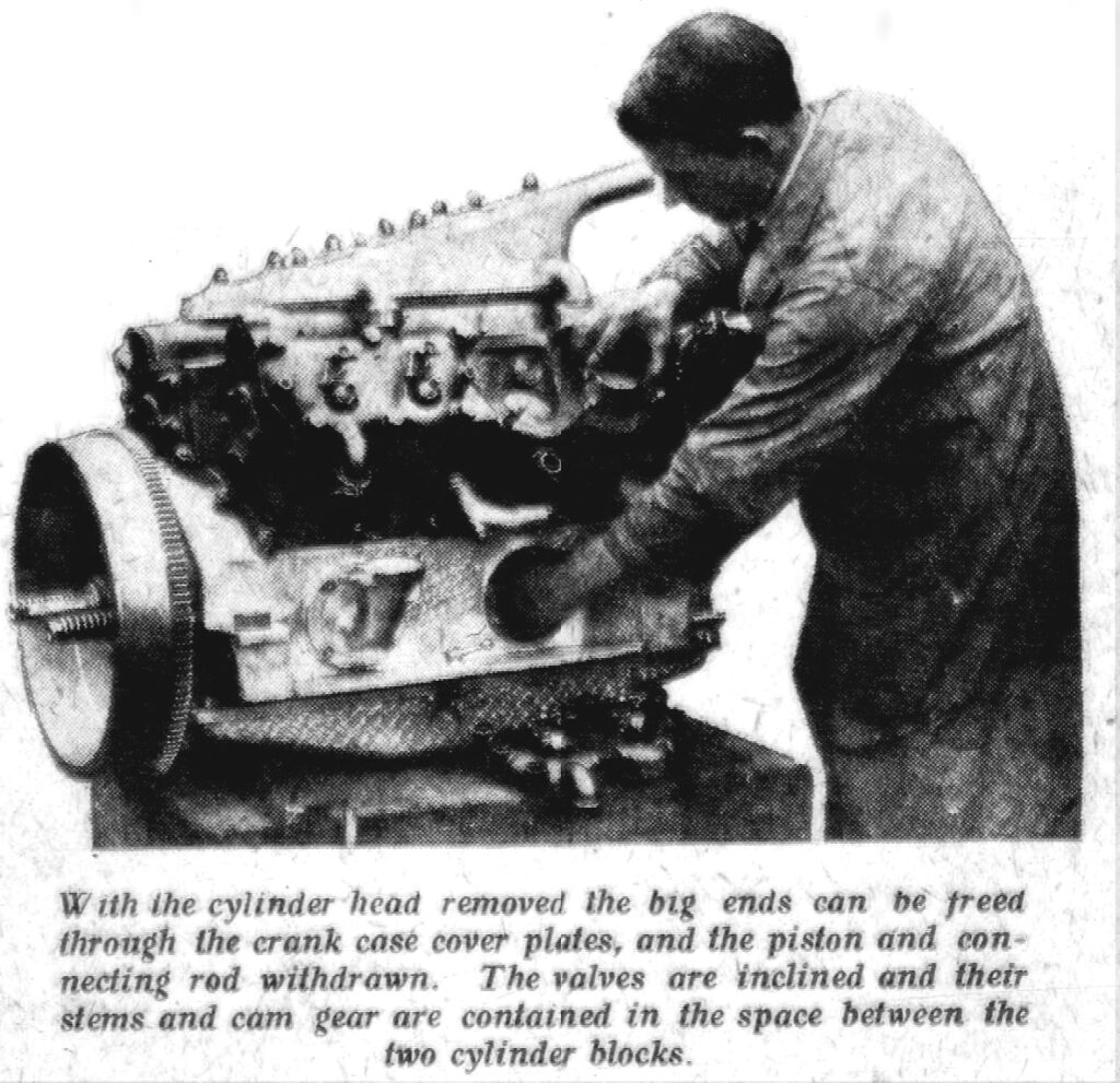
Large inspection plates are fitted to the crank-case and the big ends are designed to bolt together with the nuts on top. On account of this it is very easy with the aid of a special box spanner provided with the car, to undo the big ends and slip the connecting-rod and piston complete out through the top of the cylinder. One of our illustrations shows this being done.
Two Zenith carburettors are employed, one for each block of cylinders. Situated fairly high up on the cylinder blocks, they are fed from a large tank in the rear of the chassis by means of an Auto-Vac. The induction pipes are water-heated not by a special pipe, but by passing through the main water return pipe on the top of the cylinders. In this way a practically constant temperature is ensured, giving perfect vaporization under any climatic conditions.
Transmission Details.
The gear-box provides four speeds forward and a reverse. It is automatically lubricated by oil, as are also the universal joints, which have renewable working parts, the front one being oiled from the gear-box and the rear from the back axle. Silent spiral bevel gears are used in the back axle, the axle and shafts being fully floating. The whole of the working parts can be dismantled from the axle without removing it from the car. It is only necessary to withdraw the axle shaft, and by undoing the bolts which hold the bevel case on the front of the axle and disconnecting the rear universal joint the bevels can be taken away in mesh. Or, by undoing the back cover, the whole of the bevels and differential can be inspected. The lubrication is by oil, which is pumped through the hollow bevel pinion to the rear universal joint and along the axle shaft to the rear hub and to the rear springs, which are underslung and have small holes drilled through each plate to lubricate the leaves.
The engine, gear-box, clutch, and control are carried on a sub-frame supported by three spherical joints, which prevents any possibility of distortion of the main frame being trans-mitted to the sub-frame or the transmission. Another advantage of this construction is that in the case of damage to the main frame the sub-frame can be disconnected and the main units dropped out without interfering with them, which considerably cheapens and quickens the work in case of a repair.
The front axle is of H section, and lubrication is automatically obtained by means of two large size oil cups, one of which is situated on each of the stub axles. From these a wick feed to carefully drilled oilways ensures efficient lubrication to all parts.
No “Greasers” on the Car.
With the exception of the two oil cups mentioned above, the whole of the chassis lubrication is by means of an automatic pump feeding oil pipes running to all the parts needing oil. On the drop arm of the steering gear is a cam, which, when an extreme right-hand lock is taken, comes into action and depresses a plunger piston in the oil pump. The action of this is to force about a tablespoonful of oil into the pipe lines. These pipes are arranged as two main lines running down either side of the chassis, with subsidiary pipes branching off at intervals to the parts requiring lubrication, such as the springs, shackles, steering connections, brake shafts, sub-frame suspension, etc.
As we mentioned when describing the lubrication of the engine, the breathers in the crank-case supply oil to the valves and their mechanism, the surplus from which is trapped and delivered to the pump so that there is always a supply available. When the pump becomes full, any excess flows through a separate pipe to the steering box and directly back to the crank-case. In this way the steering box obtains a practically constant supply of fresh oil. The system is, to say the least of it, ingenious, as it is only when a full right-hand lock is taken on the steering that the pump comes into action and delivers a charge of oil. Under normal conditions, this will occur once or twice a day at least, which is ample for all usual purposes. Should it happen too frequently the pipe lines would still be full of oil, and in that case the pressure of the oil in the lines would force the new charge into the return line through the steering box and so back again to the crank-case, thus preventing an excess of oil with its consequent mess.
The steering gear consists of worm and a complete worm wheel having four keyways cut in it. There is, however, only one keyway in the shaft, so that when wear takes place in the wheel, it can be rekeyed in one of the other keyways and a new portion brought into play. In this way the entire wheel can be used if necessary.
Both the brakes are of the internal expanding variety, the foot brake, which is 12 inches in diameter, operating on the bevel pinion, and the handbrake, 15 in. in diameter on the back wheels. They can each be adjusted by hand. The method of expanding thebrake shoes is worthy of note. A sliding tongue, instead of the usual fixed cam type, is employed, and because of this the shoes are automatically compensating and bear on the whole of their surface. Another good point is the method of attaching the film type radiator. This is done by means of two ball joints, so that, no matter how much strain the main frame may be subjected to, none is transmitted to the radiator.
Electric lighting and starting is fitted as standard, and Guy Motors propose to build their own bodies. At present no price can be quoted and date of delivery is uncertain, but there is no doubt that when the car comes through in any numbers it will command a ready sale.
Motoring South Africa April 1st 1921
The Eight-Cylinder Guy Chassis
An Owner-Driver’s Car
We gave last month a brief preliminary description of the new eight-cylinder 20 hp. Guy chassis exhibited at the Rosebank Show by Guy Motors (S/A.) Ltd representing the makers, Guy Motors Ltd., Wolverhampton, England in conjunction with Bowyer’s Garage, the local agents. In the interval we have had the opportunity of examining the chassis and of observing its behaviour on the road.
Engine Details
As introduced by the makers in their excellent lorry chassis, the unique features of the Guy engine design struck the observer as lending themselves in at even higher degree to eight, than to four-cylindered construction; to an extent that the single inclined cylinder casting of the commercial vehicle engine at once suggests the absence of a companion block. Now we have the V completed simply by bolting two blocks of four cylinders together, thereby, incidentally, relieving the crankcase of a great deal of stress.
Briefly the reasons for the change to eight cylinders in the Guy passenger chassis are based upon the overlap of the impulses, with active power-delivery all the time, resulting in fluent rather than excessive power. From this comes the practicability of lighter individual cylinder effort, and hence lighter parts and higher speeds, with a compact construction and other advantages in respect of fuel efficiency from the easier cooling of the smaller pistons and so on. Coming to details, bore and stroke respectively are. 72mm and 125 mm. Four detachable cylinder heads are provided, for easy handling, each covering a pair of cylinders. The patented design of these and of the valve arrangement combines the advantages of the overhead and side valve systems. By simply undoing a few nuts the head can be removed, exposing the valves and pistons, thereby rendering valve grinding and decarbonising an easy matter. The cylinder heads are water cooled, but as the water connections are outside the heads the important advantage is secured that the joints have to withstand compression only and in the event of a water leakage occurring the water cannot get into the cylinder. The accompanying illustrations show the large crankcase inspection doors provided, facilitating adjustment of the connecting rod, big end bearings or the removal of pistons and connecting rods.
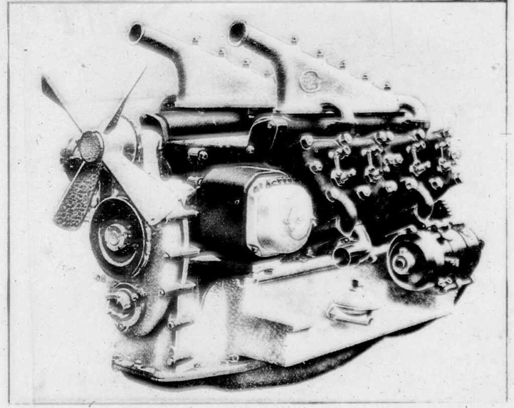
The valve operating mechanism is horizontally located between the cylinder blocks, covered in on top by means of detachable plates, and, being open to the crankcase below, operates in a mist of oil. Lubrication of the engine itself is by means of a force pump through a filter which is outside the crankcase, where it can be easily got at for cleaning. Cooling is by pump circulation in conjunction with a large-area radiator of the film type, which is highly efficient, and the radiator itself is made more effective by means of a very large four-bladed fan. A single carburettor is employed, mounted over the cylinder blocks, the induction pipe being heated by passing through the main water return pipe. Ignition is by high-tension magneto mounted high up on the off side of the engine and positioned so that the commutator end is directly facing the driver when the bonnet is lifted. The electric generator occupies a similar position on the near side, both being well out of harm’s way when deep water has to be crossed.
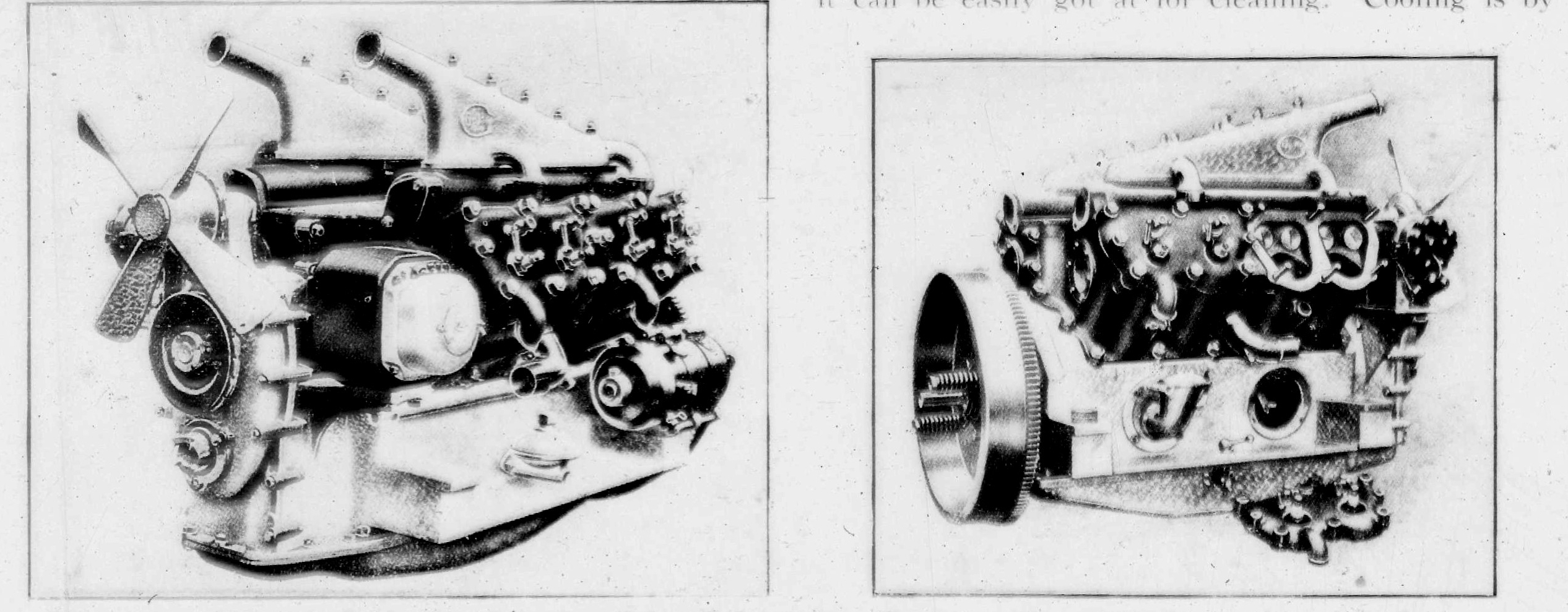
Three-quarter front and off-side view of the Guy eight-cylinder engine. The former shows the high-up position of the dynamo and magneto and the neat fitting of the starter motor, as also the oil filter on the outside of the crankcase and easily accessible for cleaning: The right-hand picture shows the water-cooled detachable heads having external water connections obviating leakage into the cylinders; also the valve position and the ease of access to valves, pistons, and connecting rods.
Showing the location of the valve operating mechanism, with one of the cover plates removed. This is open to the crankcase below, and works in an oil mist.
The Transmission.
Power is transmitted via a fabric-lined cone clutch to a four forward speeds and reverse gear box. The gear set, which runs on ball bearings, is Iubricated by thin oil, instead of grease, the encasement and bearings being of special oil-tight design. Being carried on a side-extension of the gear box, the change speed mechanism is free from any liability to jamming due to misalignment or distortion. Engine and gear box are mounted on a flexibly suspended sub-frame.
Behind the gear box is a star-type universal joint. in a stationary oil-retaining housing, lubricant being supplied from the gear box. At the other end of the cardan shaft the sliding-type universal receives oil from the rear axle, oil being also pumped to the rear wheel bearings. The axle itself is of special design, employing silent spiral bevels for the reduction gear. Axle shafts are fully floating.
No “Greasers.”
Two large oil cups are located on each of the stub axles, from which a wick feed to drilled oil-ways ensures efficient lubrication of the swivel pins and front road wheel bearings. With these exceptions, and also excluding the engine, gear box, and back axle, all parts of the chassis requiring to be lubricated receive oil through pipe lines running to a plunger pump which is attached to the dashboard bracket, close to the steering gear box, and is operated by a cam on the steering arm. Every time an extreme right-hand lock is taken on the average two or three times a day this pump is brought into action, but should this occur too frequently surplus oil is returned to the original source of supply in the crankcase.
Remaining Refinements.
Although the rest of the Guy chassis becomes less remarkable by comparison, there is no need to get under the vehicle to make any hand adjustment, and the back of the instrument board is easily accessible when the bonnet is raised. These are points which will be appreciated by owner-drivers, for whom the chassis is specially designed, and tending to ensure that the essential small amount of attention is given to keep it running at a high pitch of efficiency. Otherwise, it suffices to mention in conclusion such points as the special device for expanding the brake shoes by means of a sliding cam, to ensure equal application all round and to provide for unequal wear. Another good point is the method of attaching the radiator, by means of ball joints, so that it is completely insulated against frame distortion. Likewise, the steering, which is of the worm and complete wheel type, with the steering column adjustable for rake. Finally, not the worst point about the Guy is the semi-elliptic springing, with the rear springs underslung. The spring shackles, as may have been gathered, are automatically lubricated.
Detachable wire wheels are standard, but disc wheels can be supplied if specially ordered. Tyres are 820 by 120 Dunlop Magnums.
On the Road
Although, as tried out on the road, the chassis was insufficiently ballasted, it was evident that the complete car will hold the road in a most delightful fashion. Even for such a high-class production, in which silence is looked for, the engine was notably mute into the forties the most that road conditions allowed, the only sound being the hiss of the carburettor intake. And barring the rattling of the temporary deadweight, just strapped on behind), this absence of noise was characteristic of the chassis as a whole. For such modest engine dimensions, the power developed is really wonderful. As to appearance, the Guy is well set off by a polished aluminium bonnet, the instrument board being quite an elaborate affair of polished and mottled aluminium and handsomely equipped, whilst the whole chassis looks sturdy and bears evidence of very careful and accurate work.
The accompanying illustration of the chassis lubricating valve and operating cam is reproduced from the makers’ catalogue, in which it is acknowledged to “The Autocar.”

The Autocar October 25th, 1919
Cars to suit diverse requirements these are in quantities, but the new Guy is intended to make a direct-appeal to the connoisseur. Something better than sheer reliability and road performance is required from the modern car: it is the ability to continue at a high pitch of tune throughout the chassis, with the need for no more than casual attention on the part of the user. To give such service as this the eight-cylinder Guy has been refined down to the last detail.
Although known originally as the producers of an excellent commercial lorry, the moving spirits of Guy Motors, Ltd., Fallings Park, Wolverhampton, are by no means new to touring car work, and the success of the unique features embodied in their heavier motor vehicle is now leading the firm to adapt them to the needs of the private motorist.
In the eight-cylinder 90° V engine-a construction adopted, by the way, because of the smooth torque and the good balance as regards “end to end” rock – a special form of valve and cylinder head design is used. Two blocks of four cylinders are set on an aluminium base chamber, and between them the valves in each block are carried with their stems horizontal. Detachable cylinder heads are used, a single casting with its water jacket closing in the ends of each pair of cylinders. This arrangement, as worked out for a 90° V engine, gives most of the advantages of the overhead valve proper, but is admirably accessible both as regards valve removal and clearance adjustment. A feature of the detachable head is that the waterways are all separate and outside the castings, the gasket between head and cylinder has only to hold compression, and water cannot by any chance find its way into the cylinder. The pairs of cylinder heads are easy to remove and handle; also tapped holes are provided for the accommodation of set screws that can be used to raise the head off the cylinder when the holding nuts have been undone.
Advantages of the Design.
Other points worthy of remark are that the waterways are practically vertical and do not in any way impede the thermo-syphon water circulation, that the water passages between the cylinders, the valves, and the integrally cast inlet and exhaust ducts are ample and free, that the two last named ducts are completely jacketed, and, lastly, that the interior face of the metal into which each sparking plug screws is in direct contact with water. The plugs are situated above the centre of each piston. Covered at the top by detachable plates, the space between the two cylinder blocks is open to the crank case and contains the six-bearing solid camshaft, from the cams of which motion is transmitted to the valve stems by simple adjustable rockers carried on a single shaft. The whole valve mechanism, including the valve guides, is thus working in a mist of oil.
Aluminium pistons of the slipper type are employed, the connecting rods are H section with phosphor bronze bushes for the hollow gudgeon pins, and white metal cast in big end bearings, the bolts of the latter having their nuts above, instead of below, the bearing caps, for the reason that large covers on the walls of the crank chamber allow the big ends to be undone without its being necessary to disturb the bottom half; thus, after detaching the cylinder head, piston and connecting rod can be withdrawn from the engine.
Front view of eight-cylinder engine, showing positions of dynamo, oil filter, and starting motor.
The crankshaft is solid and is carried on three main journals, there being also a subsidiary bearing in the Cover of the timing gear, for the drive of which a Renold chain is used. Opposite number cylinders have the big ends of their connecting rods side by side on a single crank pin, and a praiseworthy feature of the engine design, as a whole, is the fact that cylinder blocks, connecting rods, valve rockers, etc., are interchangeable from one side to the other. At the front end of the engine is belt-driven fan, the bearing of which is open to the oil mist of the crank chamber. A skew gear driven transverse shaft operates through a flexible coupling the dynamo on the near side and the magneto on the off. Both these instruments are very accessible by reason of being carried high in the chassis; moreover, they are well out of the way of water should the car be driven through fords. An electric starting motor is carried towards the rear of the engine, and engages a toothed ring on the flywheel by means of a Bendix gear.
Engine Lubrication.
On the centre of the camshaft is a skew gear driving the vertical shaft of a gear pump at the bottom of the sump, which latter is screened by a gauze tray. Oil is delivered through a filter, placed high on the near side of the crank case and easy to get for cleaning, to a gallery pipe, whence it proceeds the crankshaft bearings, and onwards through the drilled crank cheeks to the big ends. A pipe leads also to the timing chain. On the off side is a large of filter with a trap to prevent foreign matter from falling accidentally into the case, and the oil level is determined by an overflow cock operated from a handle close by the filter. It should be mentioned that the main oil filter can be cleaned without letting oil out of the crank case.
Between engine and gear box is a Ferodo-faced external cone clutch operated by easily adjusted exterior springs. The clutch spigot bearing is lubricated from inside the crank case, and, to stop spinning when changing gear, a neat little brake, in the form of a second small cone clutch, is used. A single large flexible fabric joint is employed in the middle of the clutch shaft.
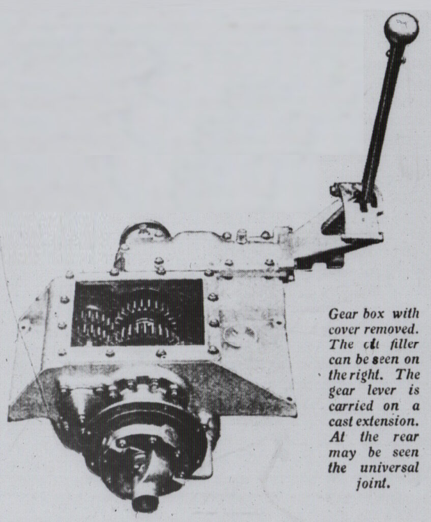
In construction the four-speed and reverse gear box is simple, the shafts are carried on ball bearings and are stout, the gear wheels being separate for ease of renewal when worn out. A proper speedometer drive is incorporated. For lubrication oil is used which is led into the box from a spout placed in a position which prevents the desired level from being exceeded. A branch bearer from me main casting carries the gate range quadrant and lever, so at these are quite free of the main frame. It may be noted at the position of this and the side brake lever relative to the front seat of the car is such as to be not only properly within reach of the driver, but also to permit the latter to enter or leave his seat easily through the adjacent wide door in the body, a feature often erroneously supposed to belong exclusively to the central change.
Flexible Suspension of Engine and Gear Box.
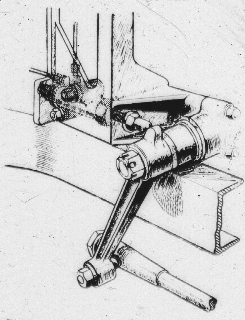
Returning to the chassis, a very important point in the construction is next reached. Engine and gear box are together carried with all their subsidiary parts on a separate sub-frame, which attached to the main frame on true three-point suspension chassis. A spherical joint carries the front of the sub-frame, and the rear ends of its side members rest in spherical joints at the ends of link levers free to rock in the fore and aft plane about the tubular cross member of the main frame on which they are slung. The object of the suspension is to insulate the engine and gear box from stress and strain set up by the main frame under influence of road inequality and shock, and also to serve the internal and comparative alignment of these parts. The Guy flexible suspension in action provides an object lesson not only of the markable contortion, the normal type of frame must undergo, but also of the freedom which this special arrangement must allow.
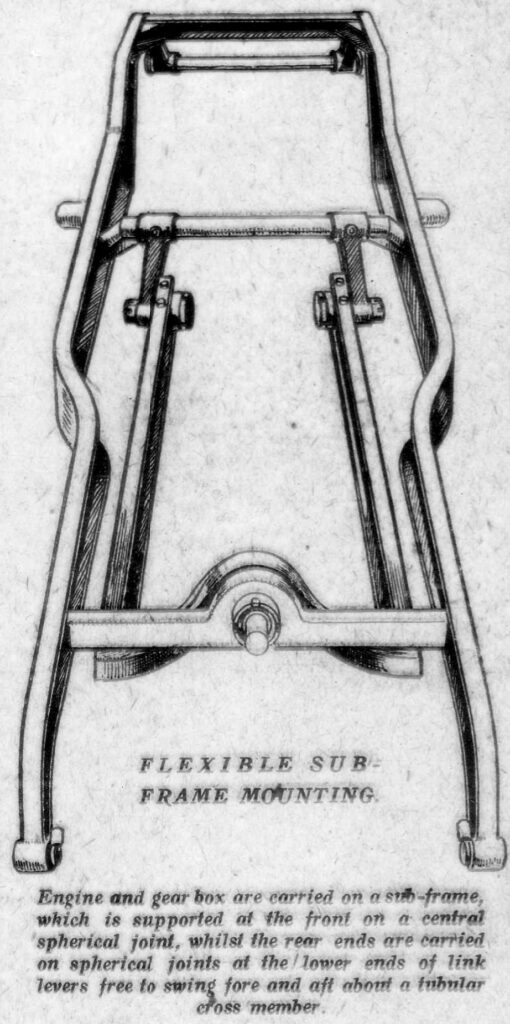
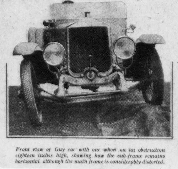
To illustrate the point we give a picture of the front of the eight-cylinder Guy car with wheel resting on an obstruction eighteen inches high. Although the main frame, as indicated by the front crossmember, is considerably twisted, the front member of sub-frame, seen below the latter, remains practically horizontal. Another indication is the gap between bonnet and radiator on the driver’s side. This V fronted radiator, incidentally, is supported and insulated by spherical trunnions.
A great point in the design is the ease with which the engine and gear box can be removed. from the car. At the rear of the gear box is a star form of universal joint contained in a stationary housing with an oil-retaining leather cover, and lubricated from the interior of the box, a feature applying to the driving and driven shaft spigot bearing also. An open type of propeller shaft with a twin square nut and pot joint is used, the bearing faces of the pot being detachable, reversible, and made of hardened steel. This joint is lubricated from the rear axle.
Of the banjo pattern, braced with a tie-rod, the steel casing of the rear axle contains a spiral bevel final drive and bevel differential, the assembly of which is carried on ball bearings in a separate aluminium housing bolted in from the front. The rear cover of the case carries a “predetermined level” oil filler. An axle more easily accessible. for gear setting, adjustment, or renewal, it would be difficult to design. Mounted on the bevel pinion shaft in the front of the casing is the drum of an expanding foot-operated brake, a position for the brake which gives the advantage of gearing up from the road wheels but does not put braking stress on the propeller shaft and universal joints. Oil from the main well is supplied along the axle tubes to the hub bearings, and also actually to the leaves of the very long under- slung semi-elliptic rear springs, which latter take, both torque and drive. Like the foot brake, those of the rear hubs are actuated through a sliding tongue cam, which ensures that both halves of the shoe bear with equal pressure in the event of unequal wear. Accessible hand adjustment is provided, and the levers can be reset for angularity when necessary.
Complete worm and worm wheel form the steering gear, the rake of the column being adjustable by means of a particularly neat bracket, and above the wheel are controls for ignition and throttle in addition to a central button for the horn. The tubular tie-rods of the steering connections are all equipped with a plug and are filled with oil which finds its way to the various ball joints through wicks. Large oil cups and a wick feed are also used for the lubrication of the front axle swivels and bearings.
Automatic Lubrication of the Chassis.
Attention is now drawn to that which forms the most important feature of this very thorough job. The owner can abolish grease from his garage, and look for his oilcan about twice a year. He is called upon to fill oil when necessary into the engine, the gear box, and the rear axle, and to inject it into the casing of the rear brake shafts, the steering tie-rods, and the front axle swivel cups about once in every six months. All parts of the car, such as the spring shackles and pins, the pedal bosses, underframe sus- pension, spherical joints, steering box, clutch withdrawal, side brake compensator shaft, etc., are positively lubricated through wick feeds, which are kept supplied from a plunger pump through steel or flexible metallic pipe lines concealed in the side members of the frame. This plunger pump is attached to the dashboard bracket close by the steering gear box, and is operated by a cam on the boss of the steering arm. The pump gives one stroke every time the car turns on an extreme right hand lock. This sounds rather curious, but reflection will show that there are no rotating shafts on the average car which rotate sufficiently slowly to give the pump about three strokes in the course of a day’s run, whereas observation has shown that a tight hand extreme lock does occur in ordinary driving with about the desired frequency. The oil supply is obtained from the engine.
AUTOMATIC LUBRICATION OF CHASSIS DETAILS.
All the important parts of the chassis are automatically lubricated through pipe lines running to a plunger pump, which is operated by a cam on the steering lover every time the car turns on a right-hand extreme lock.
Amongst the remaining refinements of the car must be numbered an instrument board, the back of which can be got at when the bonnet is raised, and a special two-way cock in the main 20-gallon petrol tank at the rear of the frame. An Autovac is used for the feed to the two carburettors, and this draws its supply through the two-way cock, one position of which opens a pipe reaching to the bottom of the tank, and the other a second pipe reaching short of the bottom. One pipe will empty the tank, and the other leave about two gallons in the bottom, and is the one normally in use, maintaining, as it were, a reserve of two gallons. The handle of the cock is so placed that it has to be turned to the normal position before the filler cap can be removed for replenishment.
The standard body is a five-seater, with adjustable front seats. The price is not definitely fixed. Free inspection, of the car for two years will form a part of the contract. Deliveries are expected to commence in May, 1920. It is desired that we should point out that the unique features of the chassis, such as the cylinder head and valve arrangement, the subframe suspension, the chassis lubrication, the steering column adjustment bracket, and reserve petrol cock are patented fully, as well as in detail.